close-up of Cobra Probe head Series 100 Cobra Probe ECA Probe Dynamic Pressure module Calibration traverse
  Turbulent Flow Instrumentation logo  
  Home Products Services Support Downloads Company  

Products

  • Cobra Probe
  • - Probes in use

    - references

  • DPMS
  • ECA Probe
  • Device Control
  • Other
  • FAQs
  • Cobra Probe

    The Cobra Probe is a multi-hole pressure probe able to resolve 3-components of velocity and local static pressure in real time. A frequency response in excess of 2000 Hz means the Cobra Probe is especially suited to the measurement of turbulent flows, although accurate mean-flow measurements are also made. The Cobra Probe is robust and easy to use.

    With real-time data display, real-time frequency analysis and support for fully automated flow mapping, the Cobra Probe is a flexible and powerful tool for flow measurement. Read on for further information or download the catalogue pages for more detailed specifications (see link below). The menu at left provides links to examples of the Cobra Probe in use, and papers that have been published about the Cobra Probe or work using it. Click on any image on this page to see a larger version.

    - Performance

    - Calibration

    - Hardware

    - Operation

    - Probes in use

    Performance

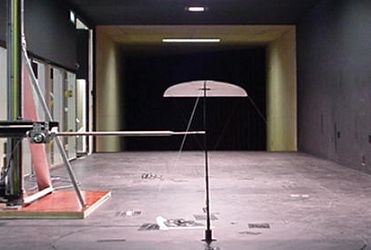
    The Cobra Probe is able to measure flow fields within a range of ±45° at frequencies of more than 2000 Hz, making it ideal for the measurement of turbulent flow fields.

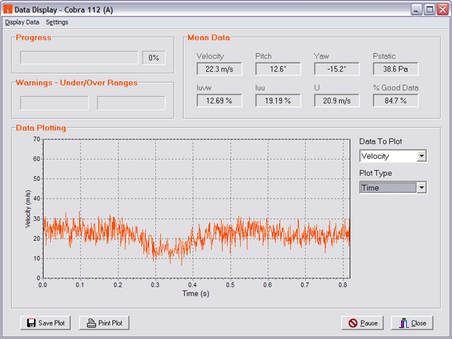
    Data obtained by the Cobra Probe include mean and time-varying values of: velocity (3-components); pitch and yaw angles; and local static pressure. Turbulence intensity and all six components of Reynolds stresses are also calculated and displayed. Other higher order terms can be calculated from the time-varying data.

    Data are displayed in real-time as they are obtained and can be saved to disk for later analysis. Real-time frequency analysis is also included - perfect for analysing vortex shedding and other periodic flows.

    Accuracy of measurements is somewhat dependent on turbulence levels but is generally within ±0.5 m/s and ±1° pitch and yaw up to about 30% turbulence intensity. The Cobra Probe remains relatively accurate to greater than 30% turbulence intensity.

    An MAV wing planform in the RMIT Industrial Wind Tunnel with a traverse mounted Cobra Probe

    Both data and frequency information can be displayed in real time

    Calibration

    Cobra Probes are supplied fully calibrated and ready to use. Probe calibrations are very stable over long periods of time and a wide range of temperatures. Cobra Probes can be recalibrated by TFI if required. Standard J, or straight, Cobra Probe heads
    Hardware

    The Cobra Probe is an almost self contained unit - it only needs to be attached to a data acquisition (DAQ) system to operate. The Probe houses the pressure transducers and other electronics. Data are measured by the DAQ system and processed by the TFI Device Control software to resolve 3-component velocity and static pressure measurements.

    Cobra Probes are generally 160 mm in length with a maximum diameter of just 14 mm. Cobra Probes are available with three sizes of head - 1.5 mm, 2.6 mm and 5 mm - with the 2.6 mm head being the most common choice as it provides the best compromise between frequency response and spatial resolution. There are also three ranges of pressure transducer available to best match the expected operating velocity. As with all TFI products, the Cobra Probe can be customised to meet specific needs.

    A Series 100 Cobra Probe with a 2.6 mm head

    3 probe head sizes are available

    Operation

    The principle of operation of the high-frequency Cobra Probe is to relate the pressure field detected by four pressure tap locations on the faceted head to the magnitude of the instantaneous local velocity vector, the flow yaw and pitch angles and the instantaneous static pressure.

    Pressure signals measured by the transducers in the Probe body are linearised to correct for amplitude and phase distortions that are generated in the tubes connecting the Probe head to the transducers. The four pressure values are then converted to non-dimensional ratios. These are used as the independent variables that are related to the four dependent variables of total pressure, dynamic pressure, yaw angle and pitch angle through pre-calculated calibration surfaces (the calibration surfaces are generated by TFI before a Probe is supplied).

    The calibration surface lookup is performed for all samples (usually 5000 samples per second) to produce time varying values of velocity, pitch and yaw angles and static pressure. Mean and time dependent data are then displayed and saved to disk, as are other data such as turbulence intensity and Reynolds stresses.

    Home Products Services Support Downloads Company

    Copyright © Turbulent Flow Instrumentation Pty Ltd